| The NOT Gate |
The NOT gate has only
one input and a single output. The resulting output is the
reverse value of the input. It is also known as the Inverted
Gate. If the input is Low,
the output is High. If the input is High, the resulting
output is Low.
NOT Gate Function
The logic gate symbol displays
a circle, or bubble, on the output where an inversion
takes place. Without the circle, we have a YES
gate, where a Low input produces a Low
output, and a High input, a High output. But as the truth
table for a NOT gate shows, the
outputs are now reversed. A Low input results in a Highoutput
while a High input gives
a Low output.
|
NOT Gate Symbol |
Truth Table |
The equivalent electrical
circuit consist of a switch shunted across a light bulb.
When the switch is open (a logic Low), the bulb lights,
producing a logic High. If the
switches closes, meaning a logic High, it shunts, or
bypasses, current, current around
the bulb and the bulb can't turn on (a logic Low).

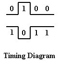
In the timing diagram, anytime
the input is Low, the output is High. Anytime the
input is High, the output is Low.
The transistor equivalent circuit
is simple enough. A Low at input A keeps the
transistor off and output X pulled High through
resistor
R2.
With
a High at point A,
the transistor turns onand point X is brought
to ground or Low.
![]()
The Boolean expression tells
us that NOT A is equal to X, or A is equal to opposite
of X. Since there are only two possibilities (Low
and High), if A is the oposite of X, is
Low, therefore A is High.
![]()