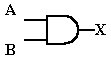
| The AND Gate | |
The
AND
gate has two or more inputs and one output. Its output will be High
only when all inputs
are High. If any or all inputs are Low, the output will also be
Low. The AND
gate is used to sense when inputs generating a High are occuring
simultaneously. It
is also used to gate through, or allow to pass, a series of pulses.
AND Gate Function
The
logic symbol displays two input and one output. The truth table tells us
that
there are four input
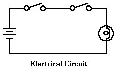
possibilities, only one of which yields a High output. The equivalent
electrical circuit
shows two switches in series with a light bulb and battery. If either or
both switches are
open (Low), the bulb wont light. Only when both switches are closed
will current flow
to light the bulb and create a High output condition.
|
OR Gate Symbol |
Truth Table |
 |
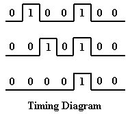
The timing diagram for the AND gate tells us that only when both
inputs are High at
the same time will
the output be High. We can say that the AND gate tests for simultaneous
High on its inputs.
The transistor equivalent shows two NPN transistors in series, similar
to two mechanical
switches in series
with equivalent electrical circuit. When both transistors conduct, the
output
at X will be
High. And both transistors will turn on only when their inputs are HIgh
and
supplying a positive
voltage to each base.
![]()
Our Boolean expression clarifies the relationship between A, B,
and X in mathematical
terms. Thus if a Low
is ANDed with a Low, the output is Low. If a Low is ANDed
with a
High, the output is
still Low. Only when a High is ANDed with a High is the output High.
X = A x B