| The NOR Gate |
The NOR gate can be thought
of as an OR gate, only, its outputs are reversed.
Where they would be Low for an OR gate, they are
High for NOR gate. Therefore,
since there are only two choices in digital logic, the
NOR
gate's output must be the
opposite of that for OR gate.
The NOR gate symbol looks
like the OR gate symbol, only, with a circle on its
output. The truth table tells us that there is only one
condition under which we can
get a High output: when all inputs are Low. Otherwise,
we always have a Low output.
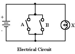
The equivalent electrical circuit places two switches
in parallel across a light bulb.
If both switches are open, all circuit current flows
through thre bulb and it lights
(output High). If any switch closes, the bulb is shunted
and it remains off (output Low).
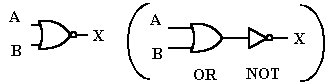
Logic Symbol |
Truth Table |
 |
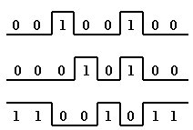
The timing diagram tells us that
only when both inputs are Low at the same time
can we gat a High output. If any input is High, the output
is Low.