
| The NAND Gate | |
The NAND gate can be thought
of as an AND gate, only, its outputs are reversed.
Where they would be Low for an AND gate, they
are High for NAND gate. Therefore,
since there are only two choices in digital logic, the
NAND
gate's output must be the
opposite of that for AND gate.
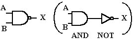
The NAND gate symbol is
similar to that used for an AND gate, with the addition
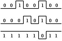
of an inverting circle on the output. The truth table
illustrates what is happening. Only
when both inputs are High do we get a Low output. Anytime
one or more inputs are
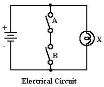
Low, the output is High. The equivalent electrical circuit
shows the logic involved,
with two switches in series placed across the output
lamp. If either switch is open,
current has only one path to flow, through the bulb (High
output). But when all switches
are close at the sme time, the bulb will stay off (Low
output).
Logic Symbol |
Truth Table |
 |
The transistor equivalent circuit
is similar to that for an AND gate except for the
placement of resistor R3
and the output X. With either input Low, the respective
transistor is cut off, no current flows, and output X
is pulled High through resistor R3.
If both inputs go High, both transistors turn on, current
flows from groud to the supply
voltage, and point X is brought Low.
|
|
 |
The Boolean expression states: "AND A and B, then invert the result".