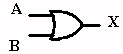
| The OR Gate | |
The gate has two or more inputs and one output. The output is HIGH when
either
or both inputs are
HIGH. It is LOW when both inputs are LOW. The gate is used to
output a HIGH when
any input goes HIGH as a result of sensor output or signal
application.
Note:
The
gate is used to output a HIGH when any input goes HIGH as a result of sensor
output or
signal
application.
Gate Function
In
the figure, we see how an OR gate functions. The logic symbol indicates
a
two-input OR
gate, while the truth table gives four input possibilities, only one of
which results in a
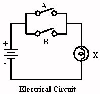
Low output. The equivalent electrical circuit shows two switches
in parallel. If one
or both switches are close, a complete path of current exists and
the bulb lights, signaling
a High output. If both switches are open, the bulb receives
no current and the
output is Low.
|
OR Gate Symbol |
Truth Table |
 |
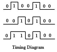
The timing diagram says that any time any input is High, the output is
High. Only
at a time when all
inputs are Low do we have a Low output.
The transistor equivalent finds two transistors in parallel, as are the
mechanical
switches in the equivalent
electrical circuit. If either or both transistors turn on, with
a high to the base,
an emitter-collector path for current flow exists and the output at
X is High. With both
transistors off, the output is pulled Low through resistor R3.
![]()
The Boolean expression simply states that when A is ORed
with B, the result is X.
If a Low is ORed
with a Low, the output is Low. If a High is ORed with a Low or
another High, the
output is High.